vacuum cleaner circuit diagram

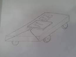
I am so lazy about cleaning my room, and it is difficult one apart from me. I think youth are facing most difficult problem is cleaning when they are staying out of their own home, me also…in this era every market has available the cleaning machine but they are high costly, or some machines are not 100%, that is why I think a plan to make an automatic cleaning robot for my final project. It is an Automatic cleaning bot It automatically moves around the room It can avoid obstacle on its path It is portable because it is a compact structure It can easily clean every nook and corner of the room Firstly, I drew a rough sketch diagram of cleaning bot, and I created a basic structural idea of cleaning bot. The main advantage of the cleaning bot is it can avoid the obstacle on its path and clean remaining area. The working concept of the cleaning bot is, in above I described one advantage of cleaning bot it avoids the obstacle on its path, for this property have I am using an ultrasonic sensor for the detection of obstacles

moreover first I am decided vacuum cleaner for the cleaning purpose but I change this process because vacuum cleaner is used to we can not clean perfectly and also very risk to clean sluggish particles instead of that I am used a rotating shaft attached to a cleaning cloth also I connected a water pump with the cloth for the cleaning purpose
remote vacuum cleaner ebay,and gear motor is
vacuum cleaner metro using for the wheel movement.
vacuum cleaner sales san jose Then I take a list of components are required for this project. I have already documented the detail of ATtiny44 microcontroller in computer-aided design week The ultrasonic sensor is measuring the properties of sound waves To elaborate it generate high frequency sound waves and evaluate the echo which is received back by the sensor, the Frequency of the sound wave above the human audible range.

How does an ultrasonic sensor working pin diagram of ultrasonic sensor module A motor driver is a little current amplifier; the motor driver function is to take a low current control signal and then turn it into a higher current signal that can drive a motor.The motor driver is using in different applications Relay and solenoid switching LED and incandescent displays The motor driver is mainly using the controlling of the motor.A motor driver is used to we can control two motors at a time H bridge bridge principle is using for the controlling process A geared DC Motor has a gear assembly attached to the motor. The speed of the motor is counted regarding rotations of the shaft per minute and is termed as RPM.The gear assembly helps in increasing the torque and reducing the speed. Using the correct combination of gears in a gear motor, its speed can be reduced to any desirable figure. This concept where gears reduce the speed of the vehicle but increase its torque is known as gear reduction.
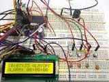
then I started the designing by Eagle software is used, before the design I think once again what are all the input and output connections are wanted from the microcontroller, the schematic diagram is shown below trace and cut part are ready for milling milled the board and I stuff the board Rhino 3D Software is used to complete the chase design work. in this 3D we can see the ultrasonic sensor fixing plate and tyre connecting places Acrylic is using for the chase creation for that laser cutter is used for the Acrylic cutting. The ultrasonic sensor is the input part of the cleaning bot.In this project I have using an ultrasonic sensor for the detection of obstacle.i am connected an external LED with my board, and I programmed in Arduino if any obstacle will come to the programming area then the LED will be blink. The gear motor is the output part of cleaning bot in here I have connected the gear motor with L293D motor driver IC, which allows DC motor to drive in either direction.

L293D is a 16-pin IC, which can control a set of two DC motors simultaneously in any direction. When both tyres move simultaneously forward the direction of the bot forward direction if left side stops the rotation, and the right side is moving forward the direction of the bot is left side else, the right side is stopped, and left side is move in forwarding the direction of the bot is right side or one side is moving forward and one side in move opposite direction the bot will rotate.Like, wise the movement will be occurring. Firstly I connected the ultrasonic sensor into the microcontroller already I discussed the connection of ultrasonic sensor, one is connected to the ground and a VCC also two input pins, input session is completed.Then I move to the output session four data pins are connected from the microcontroller to motor driver. And to get one VCC and a GND to motor driver.In here I am using 9v battery that is why I use a voltage regulator between the microcontroller and battery.

give above 5.5V directly to the ATtiny microcontroller.The cleaning process I connected a motor with switch. Water is using for the cleaning process that is why I have connected a water regulator with water storage.Ant fit with the cleaning bot.when we cleaning time the water regulator is used to adjust the waterThe immediate solution to an overload is simple: Shift some plug-in devices from the overloaded circuit to another general-purpose circuit. Then flip the circuit breaker back on or replace the fuse and turn stuff back on. In practice, however, it isn’t so easy to know that you’ve found a good, long-term solution. First you have to locate outlets on another general-purpose circuit. Then you have to find a convenient way to reach it. Resist the temptation to solve the problem with an extension cord. Extension cords are for short-term use. They’re not to be used as permanent wiring or fastened into place. To trace your general-purpose circuits, begin with the labels on the main panel.

They’re supposed to give you some idea where the circuits run. They’re usually accurate for dedicated circuits, but they’re often too vague to help you pinpoint general-purpose outlets. Chances are, you’ll have to map out these circuits yourself. To trace a circuit, turn off its breaker at the main panel (or unscrew the fuse), then go through your home testing outlets—flipping on light switches and plugged-in devices and plugging in a test light into open receptacles. Test both the upper and lower receptacle of standard duplex receptacles, because they’re sometimes wired to different circuits. And make sure switched receptacles are “on” before testing them. Check outdoor lights and receptacles too. Outlets that don’t work are connected to the circuit that’s off. Write your results down, or put them on a simple floor-plan diagram so you won’t forget or skip locations (Fig. C). Repeat for other circuits until you know what’s what. Don’t be surprised if you find general-purpose outlets on dedicated circuits.
It’s not unusual to find the family room on the same circuit as the refrigerator (Fig. A). (And remember to reset the clocks when you’re done!) Once you’ve mapped out the general-purpose circuits (even better—all your circuits), sharpen your pencil and add up the existing electrical loads on them. Fig. B shows the loads of the various lights and devices that were originally connected to one of the circuits found in Fig. A. Light bulbs usually have their wattage stamped on them. Motors are often rated in amperes or “amps” (amps x 120 volts = watts), a figure you’ll find on a plate on the motor or elsewhere on the device. TVs and other electronics usually have a watt rating on a backside label. Then figure the additional load you want to add, in this case the holiday lights. Devices temporarily plugged in, such as a vacuum cleaner or temporarily used portable electric heater, don’t count. Devices (for example, holiday lights or an often used electric heater) with long-term uses do count.

A circuit is overloaded if: A. The total load exceeds 1,800 watts for a 15-amp circuit. (120 volts x 15 amps = 1,800 watts.) Look for the amp rating of the circuit in tiny numbers on the circuit breaker switch or fuse. For a 20-amp circuit, the load limit is 2,400 watts. B. On a multiple-outlet circuit, you find any appliance or equipment rated at more than half the circuit rating, 900 watts for a 15-amp circuit. (These large-draw appliances should have dedicated circuits.) Upon checking, we found that the example circuit in Fig. A exceeded both the 1,800-watt limit for a 15-amp circuit and the 900-watt limit for any one device. The best solution to solve this overload situation is to run a dedicated circuit to the biggest load. In practice, to avoid high installation costs, professional electricians run new circuits to the appliances they can reach most easily. In our case, a professional electrician would run two new circuits, one to the refrigerator (700 watts) and another to the outlet handling the heater (1,000-plus watts).