vacuum cleaner motor resistance
In this video Mat explains how to use a meter to trace a problem in a simple electric circuit like on a mower, strimmer, vacuum cleaner or other motorised device. Hi I'm Mat from eSpares. In this video I'll be showing you how to fault trace on a small appliance, every simple appliance works by having a current running through it. This current begins at the plug, the live pin on the plug which comes up through the cable, through the switch through the motor, back up through the switch through the cable and out through the neutral pin on the plug. If there's a break on any part of this circuit your small appliance will not work. Safety first: always unplug an appliance before carrying out any work. This technique can be used on vacuum cleaners, trimmers, lawnmowers, steam irons even something as simple as Christmas lights. So what you need to do grab yourself a multimeter set it to the resistance setting and put the probes on the neutral and live pins on the plug.

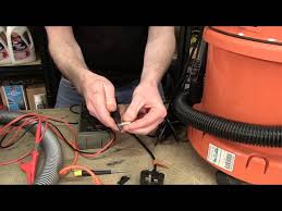
Here we can see we have a reading of 6.2 ohms. If I turn the switch off on this vacuum cleaner you can see that the reading changes to zero, no resistance. This is the same reading as if the probes were attached to nothing therefore this machine has no fault. However if I attach the connectors to the live and neutral on this vacuum cleaner, as you can see there is no resistance reading even if I turn the machine on and off via the switch the reading does not change. Therefore there is a fault in the circuit of this machine. So the first thing I need to test is the fuse within the plug, if I take that out I can again use the multimeter to test. One probe on one end and one probe on the other and you can see we have a low resistance reading, therefore there is no fault in the fuse. If I returned the fuse to the plug, the next place we need to check is where the cable meets the switch. In order to do this I need to remove the top of the switch cover. With the switch cover off, you can see that we actually have a loose connection to the switch.

Now this is something that we fabricated in order to best demonstrate fault finding, in reality it may well be that you don't have a loose cable, in that case you'd have to check the switch itself again using the multimeter to the probes, if you have a lower resistance reading on the switch there is no problem with the switch and the problem may well be with the cable where it enters the machine. If that's the case you would measure from the switch to the plug to find out if the cable is faulty.
samsung vacuum cleaner baby commercial In a lot of motorized small appliances the main problem is with the motor itself.
jual filter vacuum cleanerHere we have a typical vacuum cleaner motor, most motors contain carbon brushes, now I've started to take the carbon brush out so I'll just take that fully out to demonstrate.
vacuum cleaner francais
Carbon is an electrical conductor, the current runs through the carbon brush through the motor and back out through the switch. These carbon brushes are in spring loaded holders, so what this will do is extend the carbon brush making sure that it's constantly in contact with the metal part of the motor to complete the circuit. What happens is that these carbon brushes wear down overtime, so much so that the carbon no longer touches the metal part of the motor, therefore not completing the circuit and you'd have to replace the carbon brushes. We hope this video has been helpful in helping you to identify a fault in a small appliance. Remember spares for most appliances can be found on the espares.co.uk website.This item requires a subscription to Proceedings of the Institution of Mechanical Engineers, Part C: Journal of Mechanical Engineering Science. Already an individual subscriber? Remember my user name & password. your user name or password? Can't get past this page?

- You may purchase this article for US$40.00. You must download your purchase, which is yours to keep, within . Regain Access - You can regain access to a recent Pay per Article purchase if your access period has not yet expired. Sign in via OpenAthens : If your organization uses OpenAthens, you can log in using your OpenAthens username and password. Contact your library for List of OpenAthens registered sites, including contact details. Login via your institution : You may be able to gain access using your login credentials for your institution. if you do not have a username and password. Click here to subscribe to the print and/or online journal. Click here to recommend to your library. Email this article to a colleague Alert me when this article is cited Alert me if a correction is posted Similar articles in this journal Download to citation manager Articles by Park, C. Articles by Chang, K.

More about this journalWhen Engineers talk they want you to know that they are very smart and have their own language just to prove it... Kinda just like "COP TALK" ie: "the perp exited the vehicle and entered the establishment at which time he secured the purchase of a coca-cola product just prior to re-entering his vehicle ...." For electrical or electronic purposes: "Drawing" means consuming, pulling or using some resourse....Just as you may "DRAW" the milk up the straw from your cup, which is the source, in electronics you can "DRAW" more current from the source. Used almost exclusively in the term "Drawing Current" "Current" is a term we use to visualize/represent/measure electricity running through a wire. When people say a device is "drawing current" they simply mean that the device is pulling or using power from the power supply. In electronics we are always obsessively worried about how much juice our devices are requiring or currently using. Maybe we are worried because we are using a battery and we are worried we may kill the battery if we "DRAW TOO MUCH CURRENT" Or perhaps we may have a problem with a device.

Maybe it doesnt turn, or light up, or make the correct sounds.... BUT!!, it does seem to be "Drawing a lot of current" Thats valuable information to the troubleshooter and it sure does make you sound smart to people that dont know what you are talking about. A "LOAD" is simply a device, or part of a circuit that is using power from some electrical source. When looking at an electrical circuit that operates something such as a washing machine, air conditioner or hard drive in a computer, we say that component represents or is in fact "THE LOAD" of the circuit.The amount of LOAD can change depending on what the device is doing at any specific time. Alternatively, the "LOAD" may also be referring to the total amount of power that is being pulled from the power source. So, we may also say, "The air conditioner is putting a heavy LOAD on our circuit or collectively the air conditioner, washing machine and the computer is too much LOAD for a single household circuit. When a device is under load that means it is doing work and it needs more power from the power source or, "Power Supply".

You may/will see the term, "It is under heavy load" Obviously, HEAVY LOAD gives the idea that the device is working very hard, perhaps near its maximum capability. A light load assumes the opposite and also obvious. So the correct question is not really why does a device under load draw more power, it is really more of an understanding of what the term load actually means in this complex Engineers vocabulary. The fact that a device is "Under load" actually directly means that the device is simply using power or current from the supply. So, for any specific circuit, the heavier the Load becomes, the more current or power will be taken or drawn from the power supply. A circuit that is NOT under load is not drawing any power or current at all. Please note that "Power" and "Current" have been used in my explanation just as a generic way to describe electrical energy being used by a device or circuit. Technically, "Current" and "Power" although they are both directly related, are 2 different measurements and have 2 different values for any given circuit.

I hope this helps and hits the heart of your question..I only saw the top portion of your question about drawing currents and loads... Throwing in the motor thing shows me that you have a higher level of understanding than I was actually writing for. Now the motor thing does throw in a bit of a monkey wrench into things simply because of the incredibly interesting things that actually go on when a motor is running. It seems pretty obvious that any device that has a heavier load will require more power to operate. For example a motor that is currently lifting 10 lbs should pretty much draw double the power when the weight changes to 20lbs. Not exactly though, due to many reasons like friction and other factors, but suffice to say that logic would dictate that a machine that does double the amt of work should use double the energy (everything else being equal). So in a way, "LOAD" may be fairly described as the amount of work a machine is doing. So, the heavier the lifting in our example, the heavier the LOAD, the more power is required.

So looking at the motor thing strictly as a DC Ohms law thing, and considering your level of understanding, there should not be any question why a heavier load will increase the current in a circuit. When the load gets greater, effectively the resistance of the load decreases. So if the applied voltage stays the same but the load resistance goes down, obviously the current must go up. Only problem is, the numbers dont work. Looking at this from a straight Resistance, Voltage, Current relationship, the motor thing doesnt seem to make electronic sense. The numbers dont calculate out the way you thought. And this is the exact reason that I chose not to pick AC theory or communications as my major field of study. When you get into these theories, things start to appear to break the old OHMS law thing. Notice I said appears. When you finally sit down and do 4 pages of mathmatical equations, all based directly on and in accordance with ohms law, it all works out and proves out to be exactly what they said should happen even though it doesnt seem to make sense at first glance..

What is actually going on in a motor when it is running is a complex series of interracting events that are all affecting the current flow in their own way. Along with friction, heating of the windings, and some other minor things taking place, there is something called counter EMF. This is the most influential factor believe it or not. When you are running an electric motor(lets please just stick with a dc motor for our purposes. My brain is already starting to hurt just thinking of trying to explain the AC motor.), theoretically the only power that is consumed is the loss in the friction of the bearings and the coil windings. Otherwise an electric motor would "theorectically" draw no power. Because of the design of the electric motor, it actually generates its own electricity. Just as a transformer or electric generator work , the electric motor also employs the idea that a charging coil of wires will actually contain energy in the magnetic field that surrounds itself when a electric current is passed through it.

When this field collapses, it induces a voltage on the surrounding coil of wires 100% equal and opposite of the current that was used to charge the coil initially. (minus the losses in the coil.) This is called the counter EMF. In a Transformer or generator device, the resulting electrical current produced is sent to its load or power supply to be used as needed. But in the electric motor, this reverse current flows back into its own power supply having the effect of seemingly replacing the current that was originally pulled from it. Now add in the heating of the wires, the effect of the permanant magnets that are also part of the DC motor, and other factors and for me at least, it becomes mathmatically imposible to calculate.... Well, not really, but...Get a Watt meter and measure the actual power. Do the math one time in your life to prove out the theory but after that just trust the Watt meter. If you attempt too many of these type calculations in your life time your head will explode so please use extreme caution.

One thing missing from the above explanation is that although we were talking about a dc motor we are still dealing with an alternating current building and collapsing on a coil because as a DC motor rotates, it is constantly reversing the polarity of the charge in the coil wires effectively producing an AC voltage. This could probably take a lot bigger and better explanation but i got to cut it off somewhere. Ok, so now to explain why the current increases when the motor is held back or even stopped while full power is still applied. Now that the motor is stopped lets say, the magnetic field around the coil never collapses. Without the motor turning you are simply running full voltage directly into a straight piece of wire. A long coiled wire perhaps, but still not much electrical resistance. So without the on and off switching from the rotation of the motor, the full voltage from the power supply is constantly applied to the motor coil. Then the coil starts to pull massive amounts of current from the supply and at the same time heating up the coil wires trying to expell this basically shorted energy.